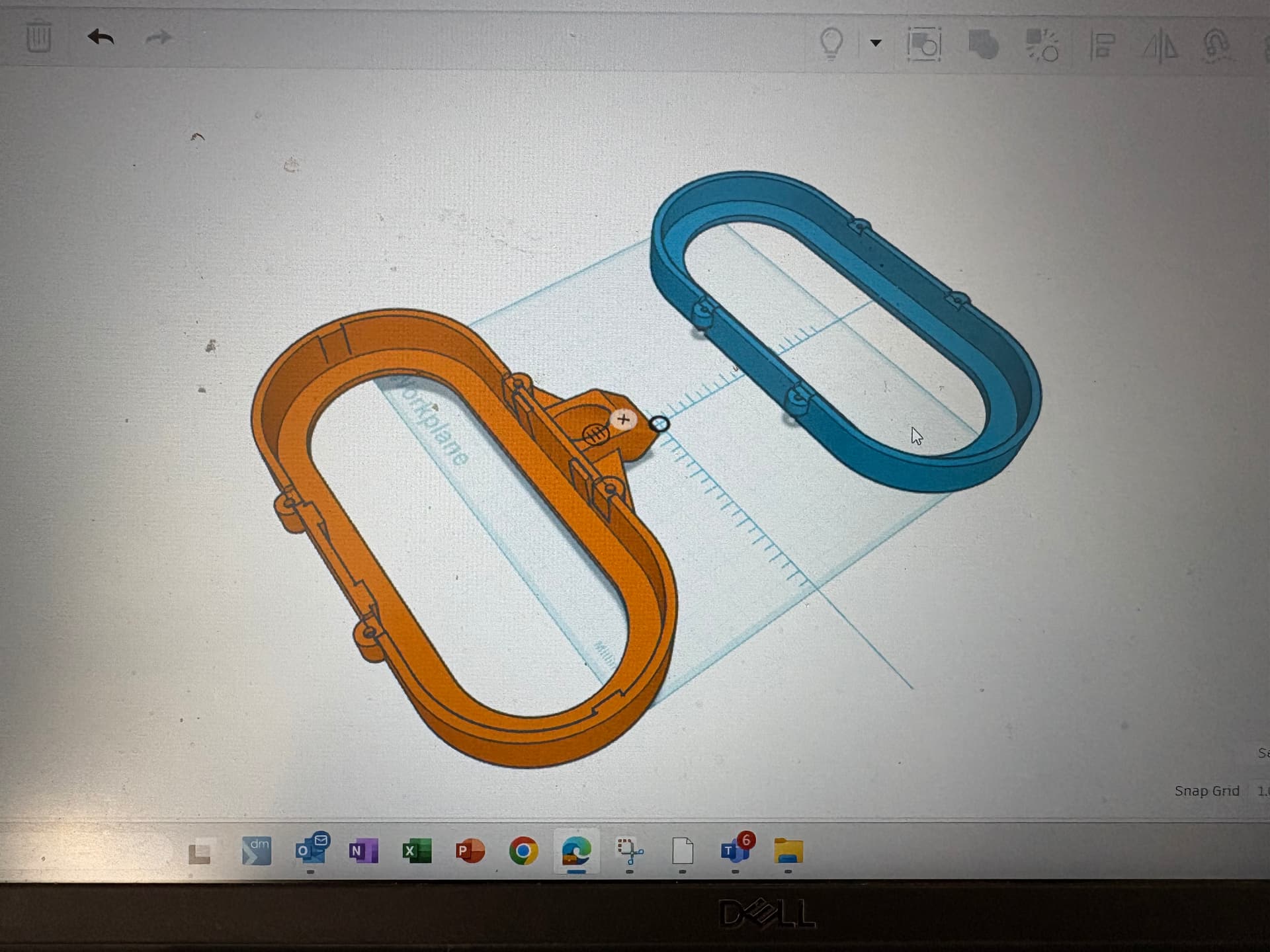
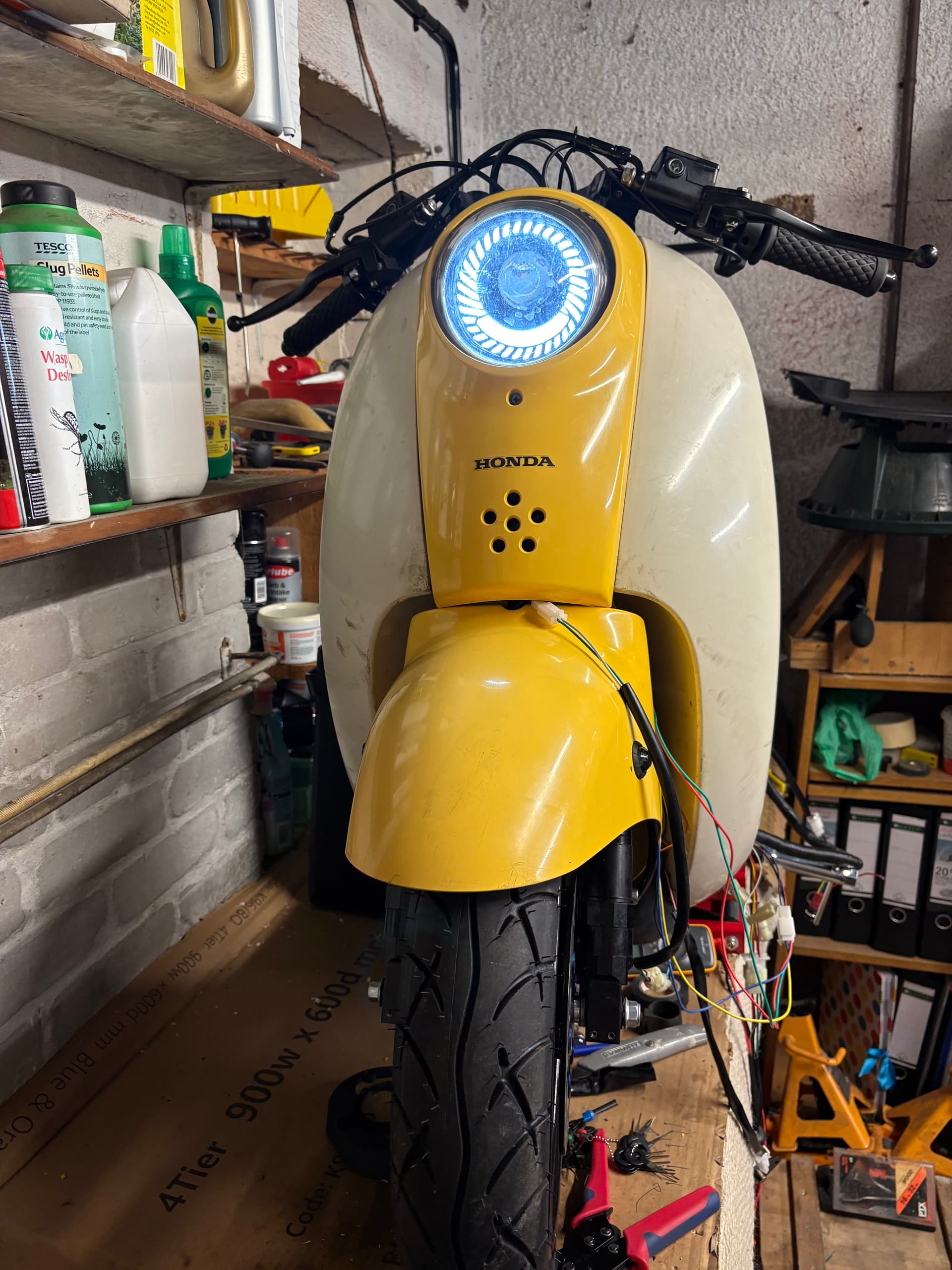
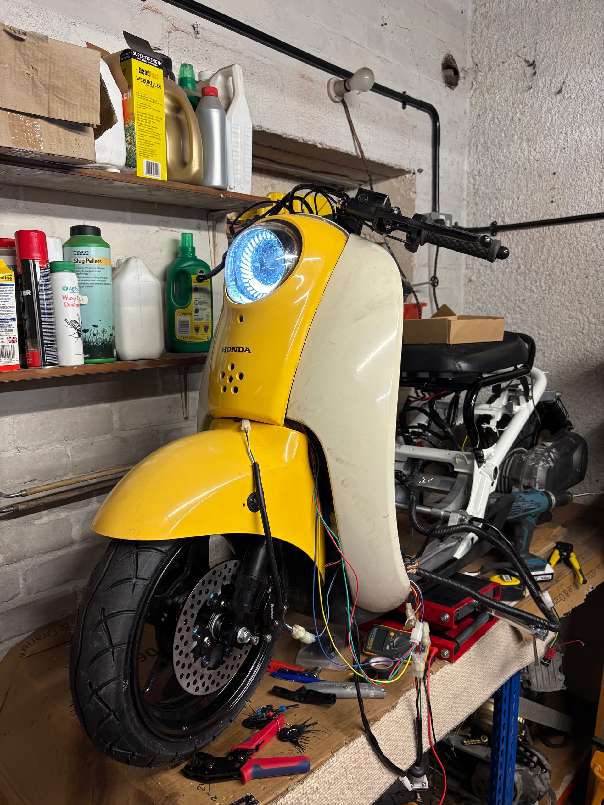
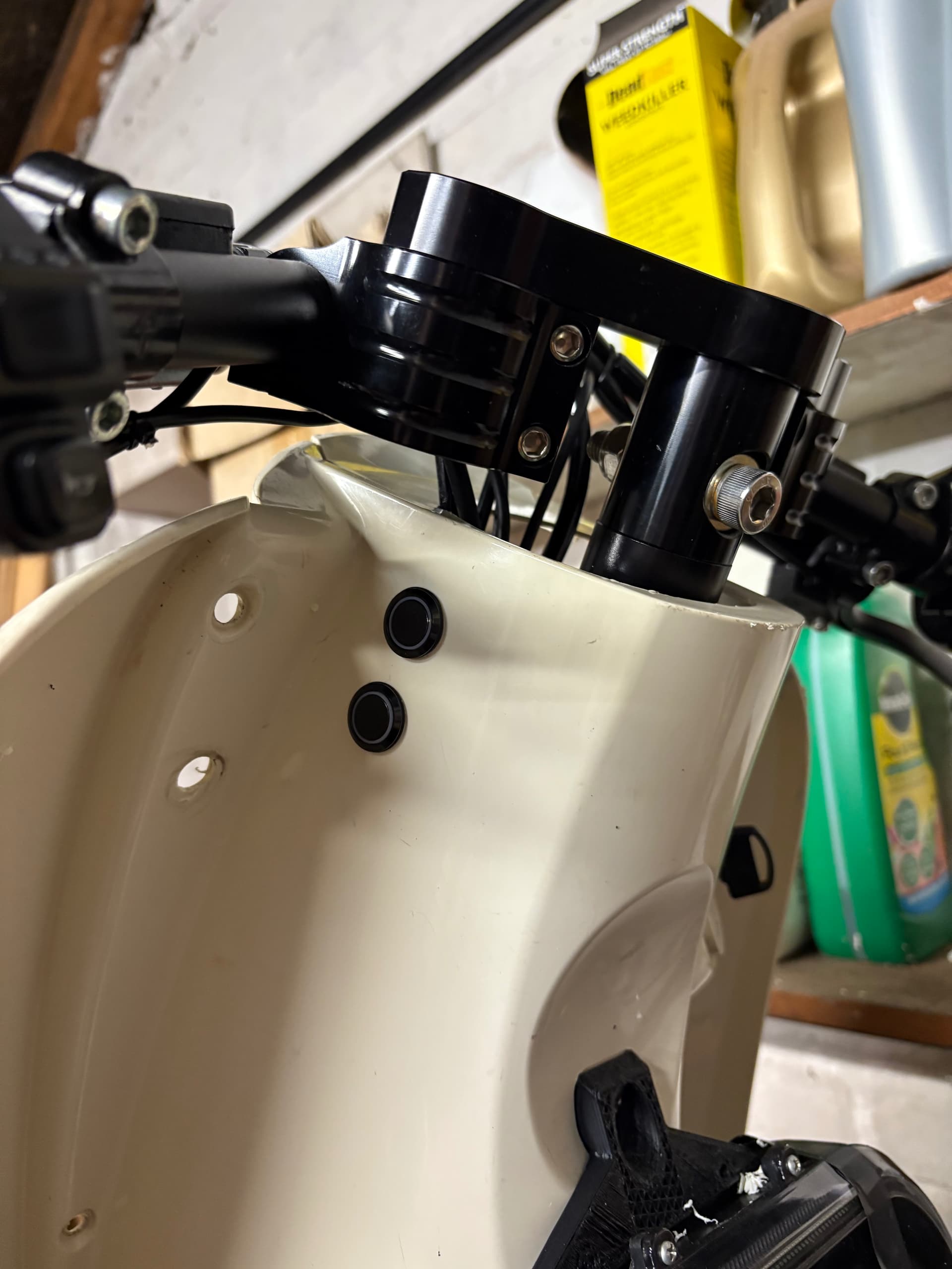
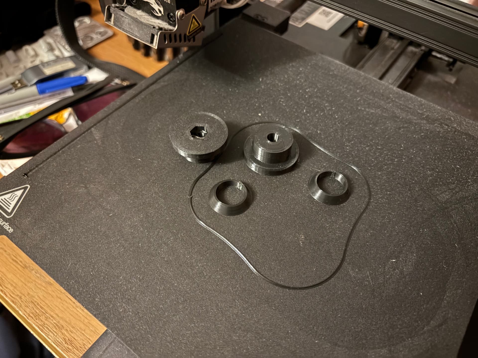
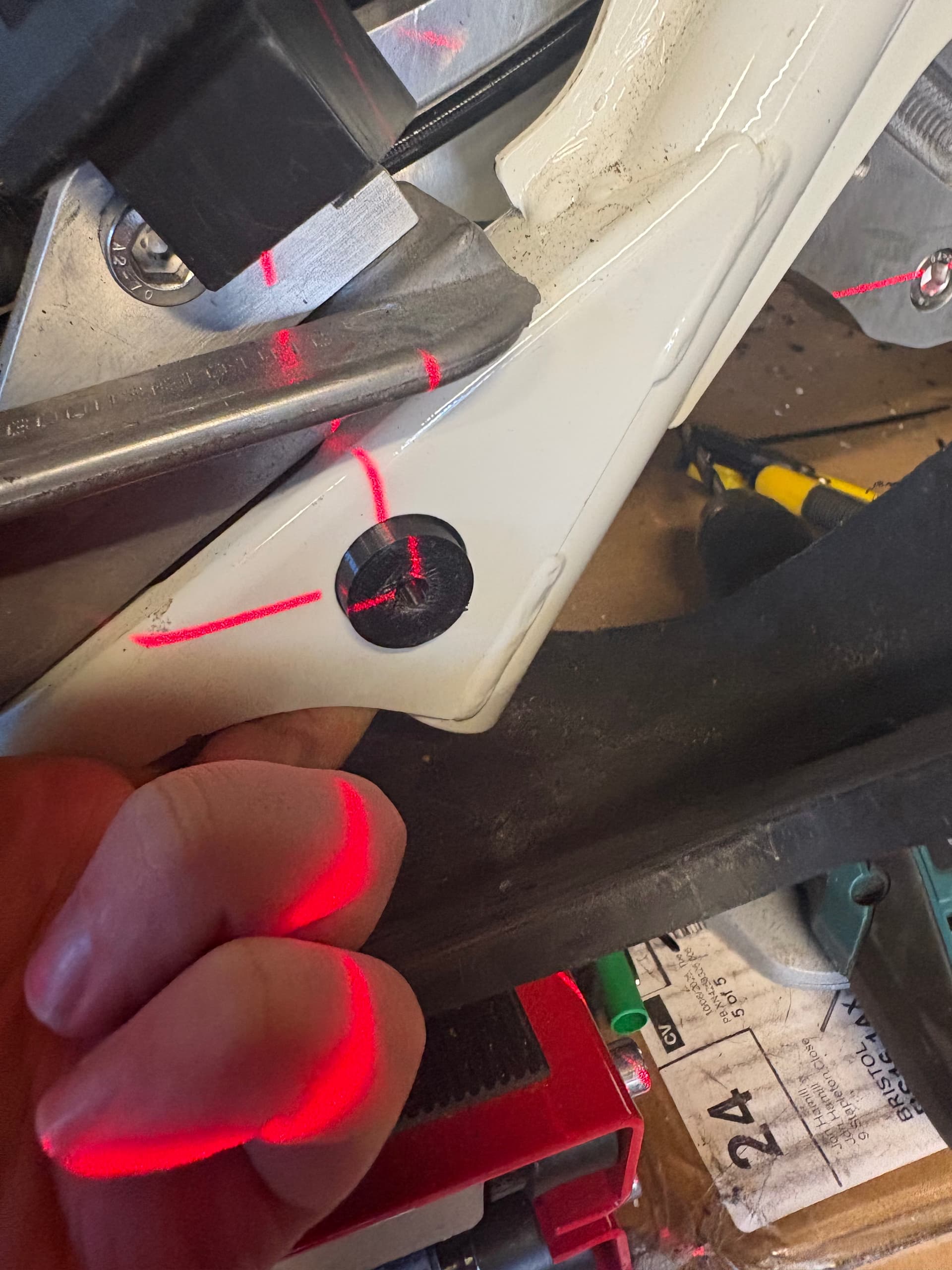
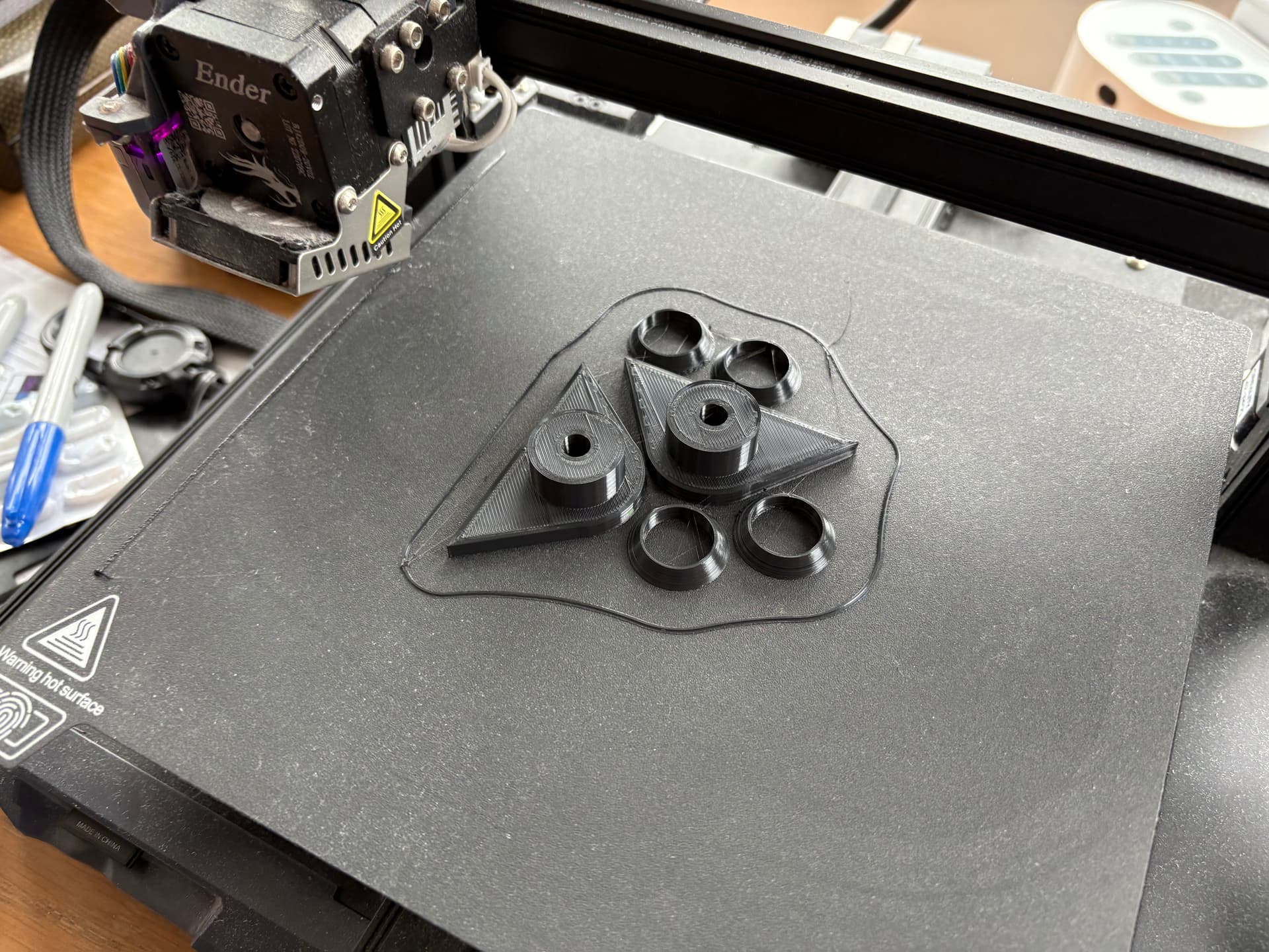
Here is the latest version of my headlight bracket…
And
Accuracy of Designs
Its not perfect. It is made specifically for my set up (my light and the amount I have cut off) so may need adapting to suit your own requirements.
I am not responsible for the accuracy, functionality, or suitability of the 3D designs. All final designs and uses must comply with applicable laws and regulations.
I cannot make any update to the model to suit your needs - this is your responsibility.
Intellectual Property
This is my design, and I own the intellectual property - I will not be held liable for intellectual property disputes. This is for use as Non-commercial, meaning you can’t sell it, but you can 3D print it for personal use.
License
Attribution-NonCommercial-ShareAlike 3.0(CC-BY-NC-SA 3.0)
This license lets others remix, tweak, and build upon my work non-commercially, as long as you credit me and license your new creations under the identical terms. More info on Creative Commons licenses
Prohibited Uses
You are responsible to check if the design violate laws, including but not limited to those that infringe copyrights, trademarks, or patents, or that facilitate illegal activities.
Quality and Material Limitations
3D printing is subject to inherent limitations in material strength, surface finish, and dimensional accuracy. You should evaluate designs / printed parts for suitability in their intended applications.
Liability Waiver
I am not liable for any damages, injuries, or losses arising from the use of the design / printed products. You assume full responsibility for the application of design / printed items.
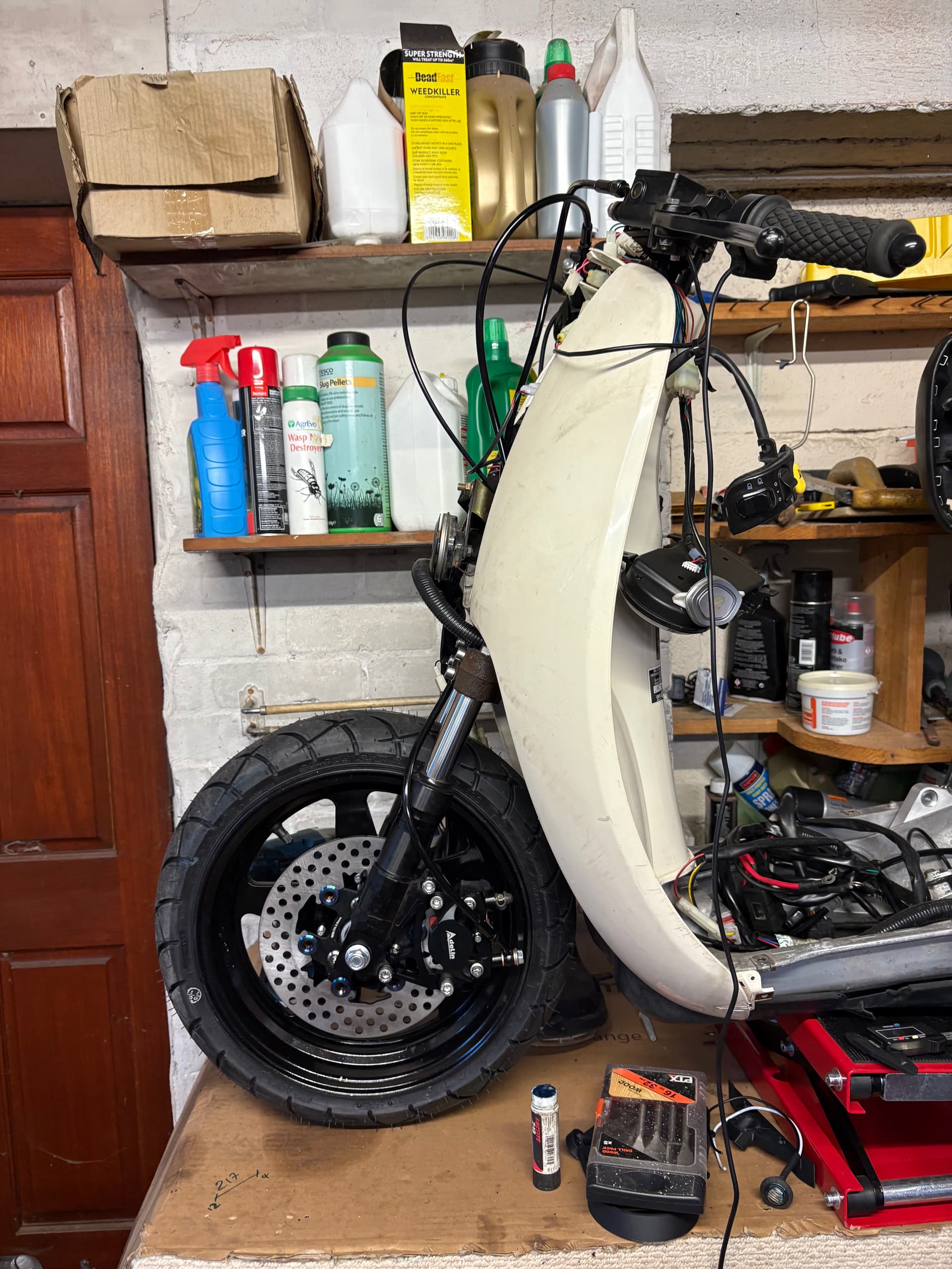
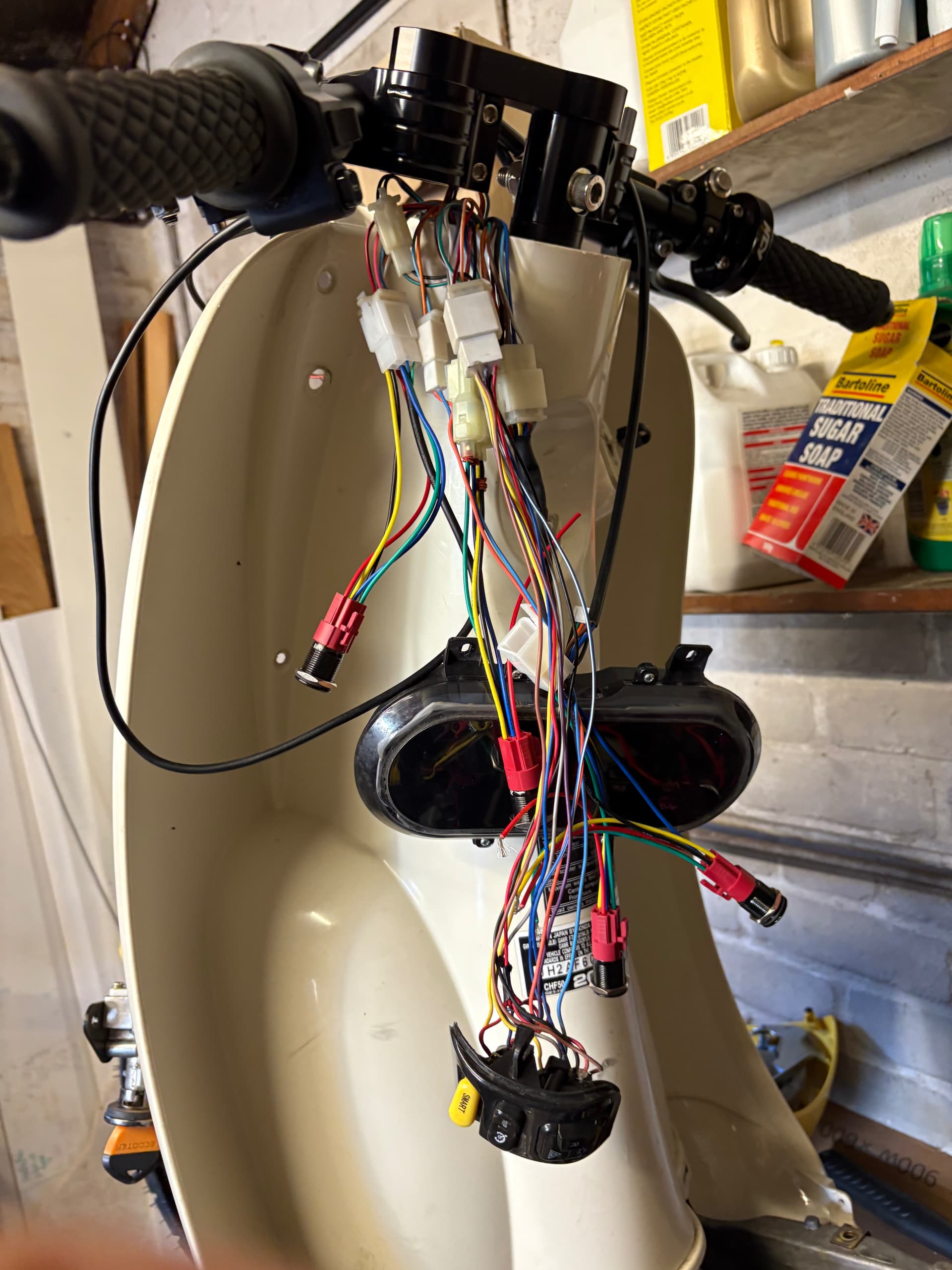
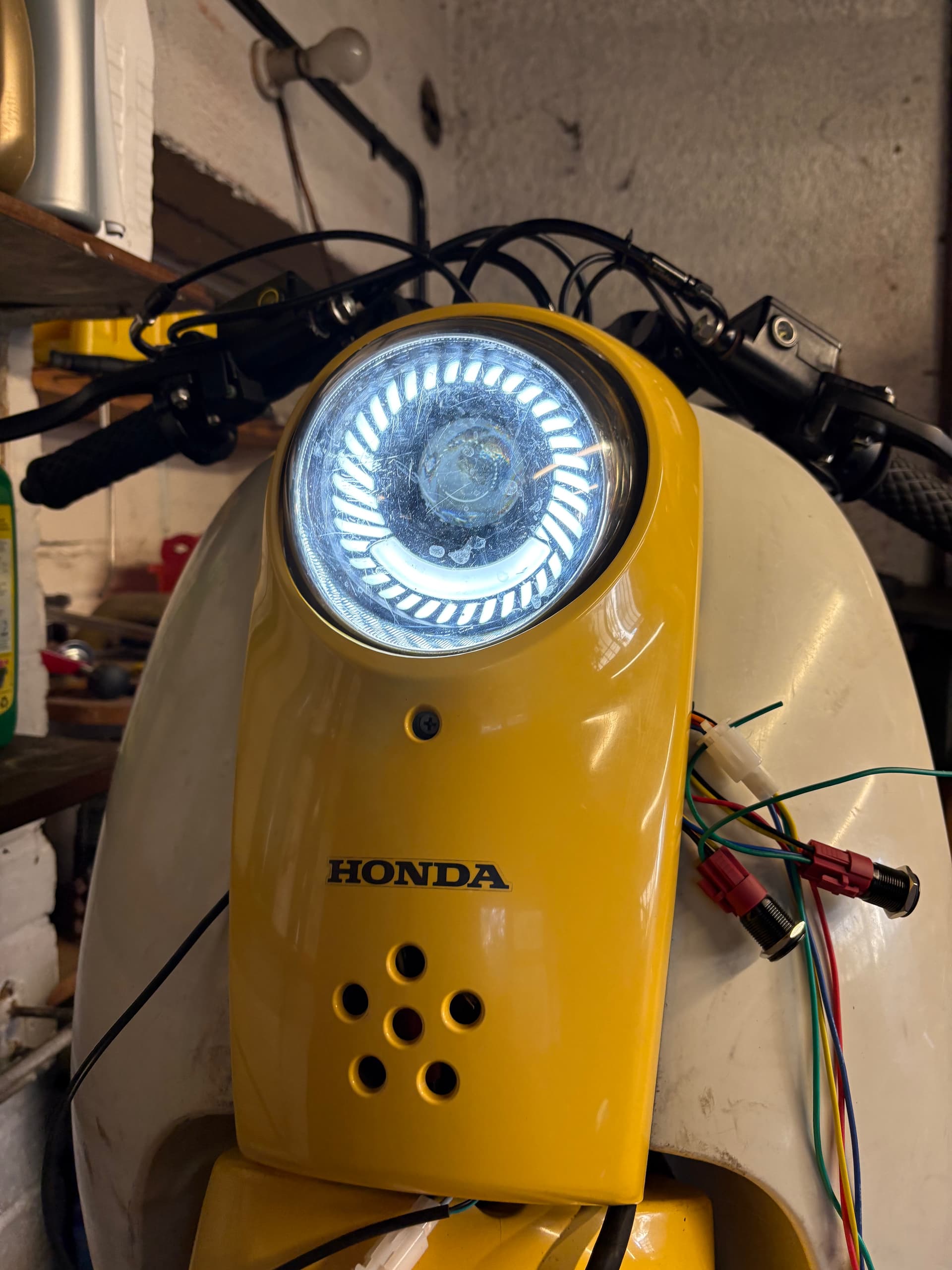
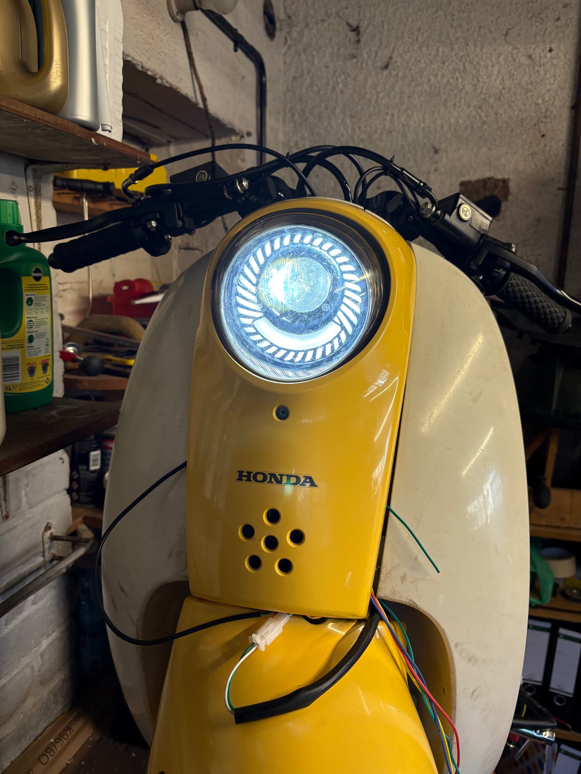
The indicators aren’t working now I’ve swapped them over… might be a load thing… will try a variable relay. Went with the same button LEDs as on my Met and fender mounted.
Everything works except the front indicators. Not sure why at this point. Have ordered a variable relay to test, but the rear indicators work, so not sure.
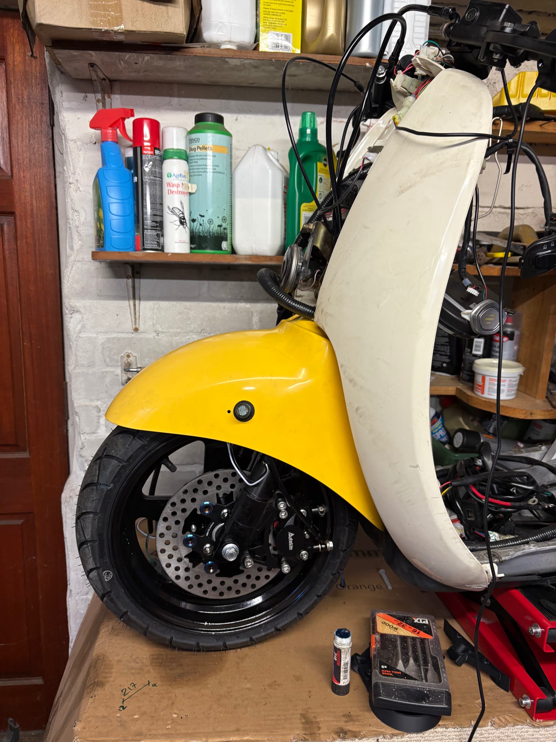
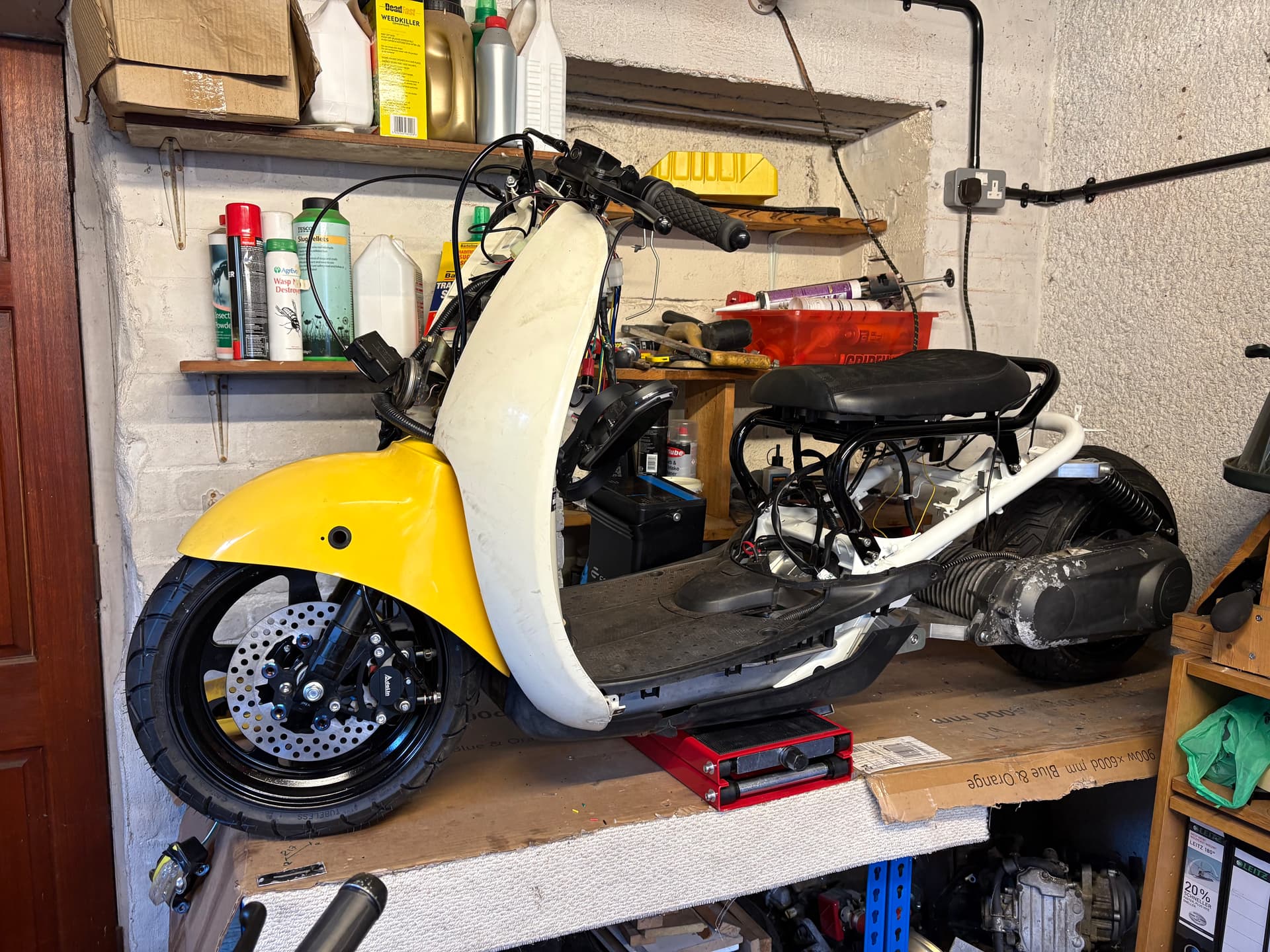
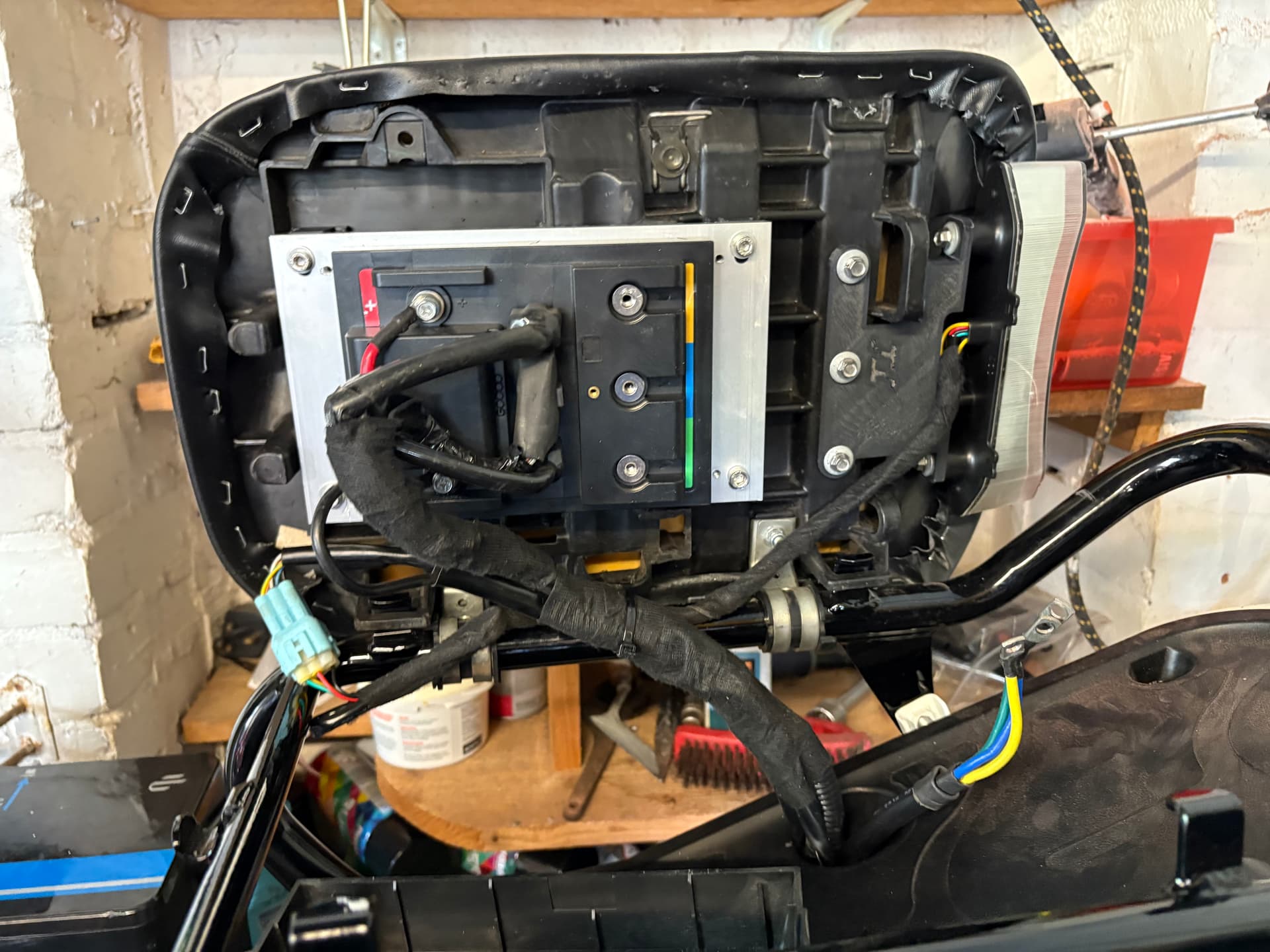
Have been spending time getting the loom in the right place…
I wanted the lights and high beam on the other side to mirror but they foul the cables when turning, so I might mount them on the bars if I can find a nice looking set.
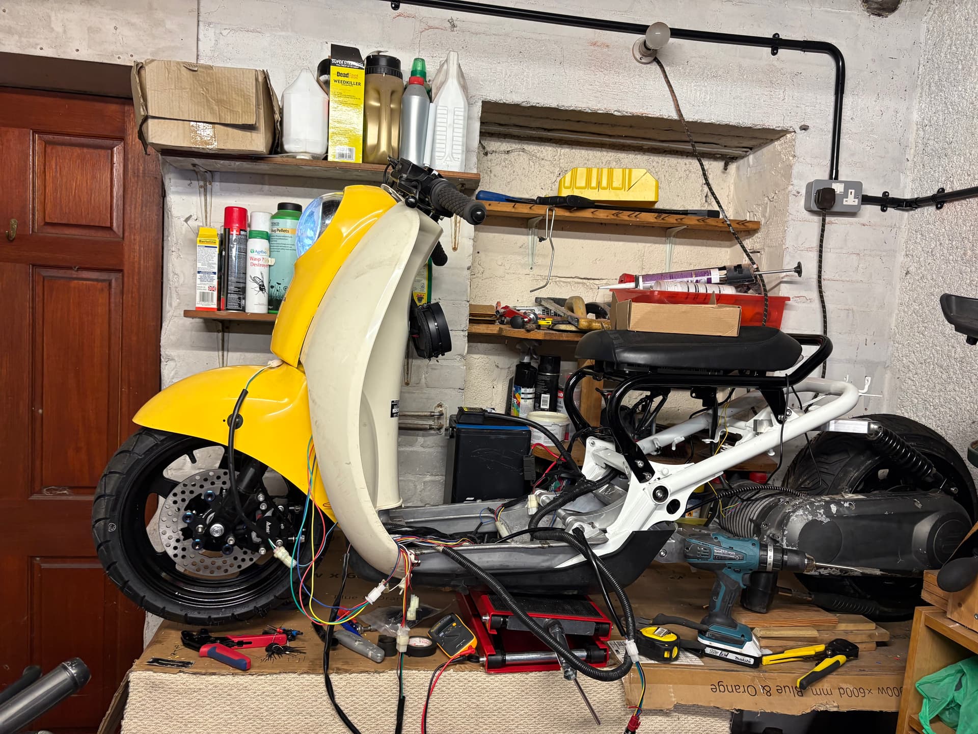
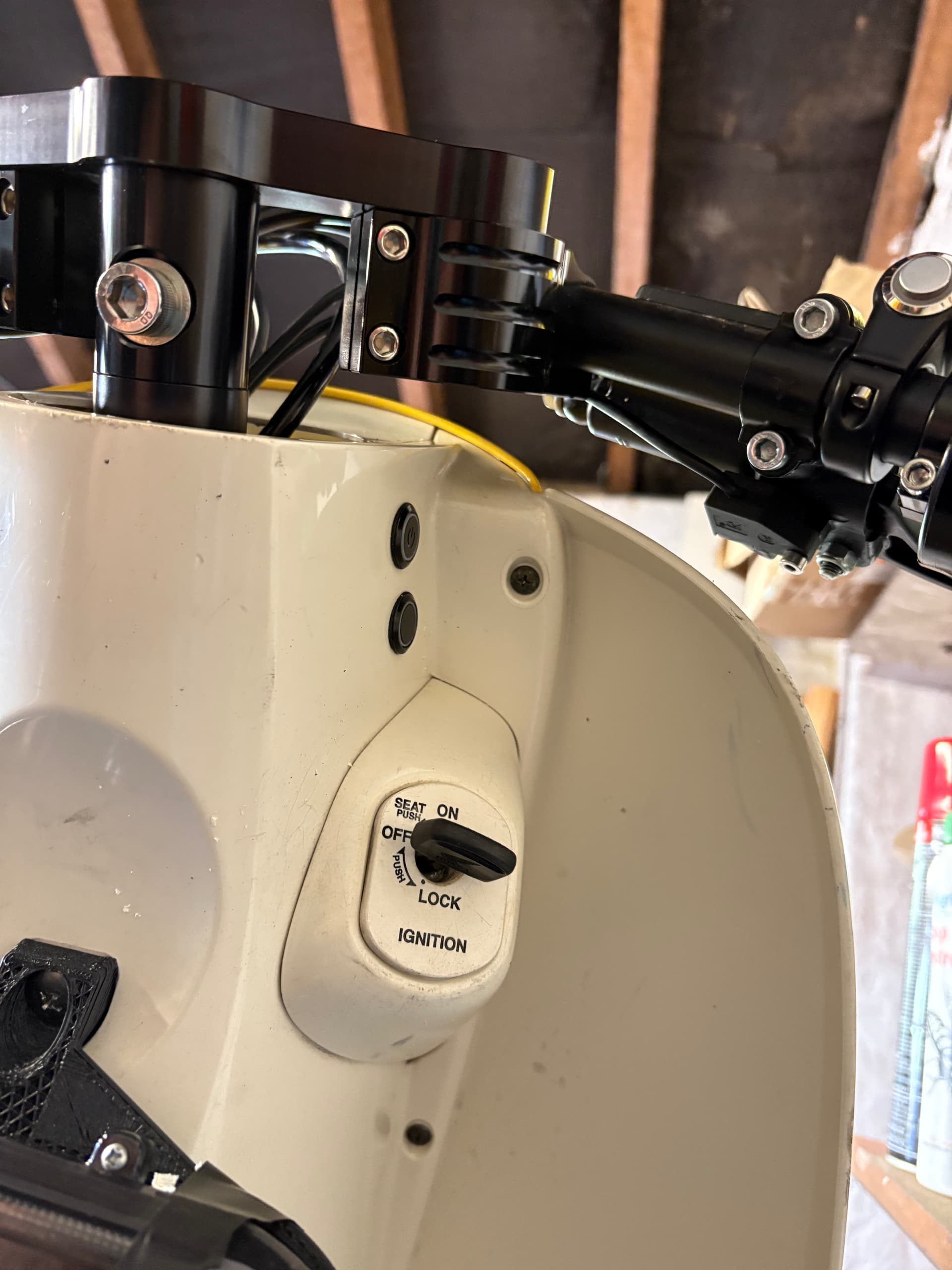
I’ve put the parking button and charging dock on the front of the rear plastics. Not sure if I like the location of the charging dock, but I’ve cut it now so will leave it there for the moment.
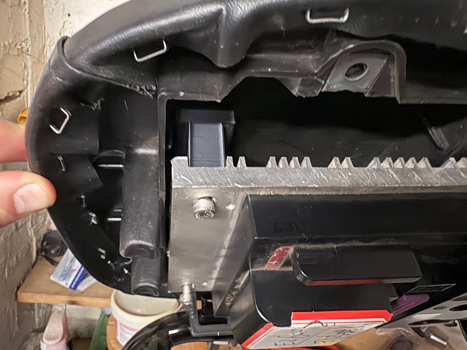
I think you could maybe start with the floorboard plastics cut the space out and then make some kind of cover that goes over the original. Honestly, can’t wait to see what you do.
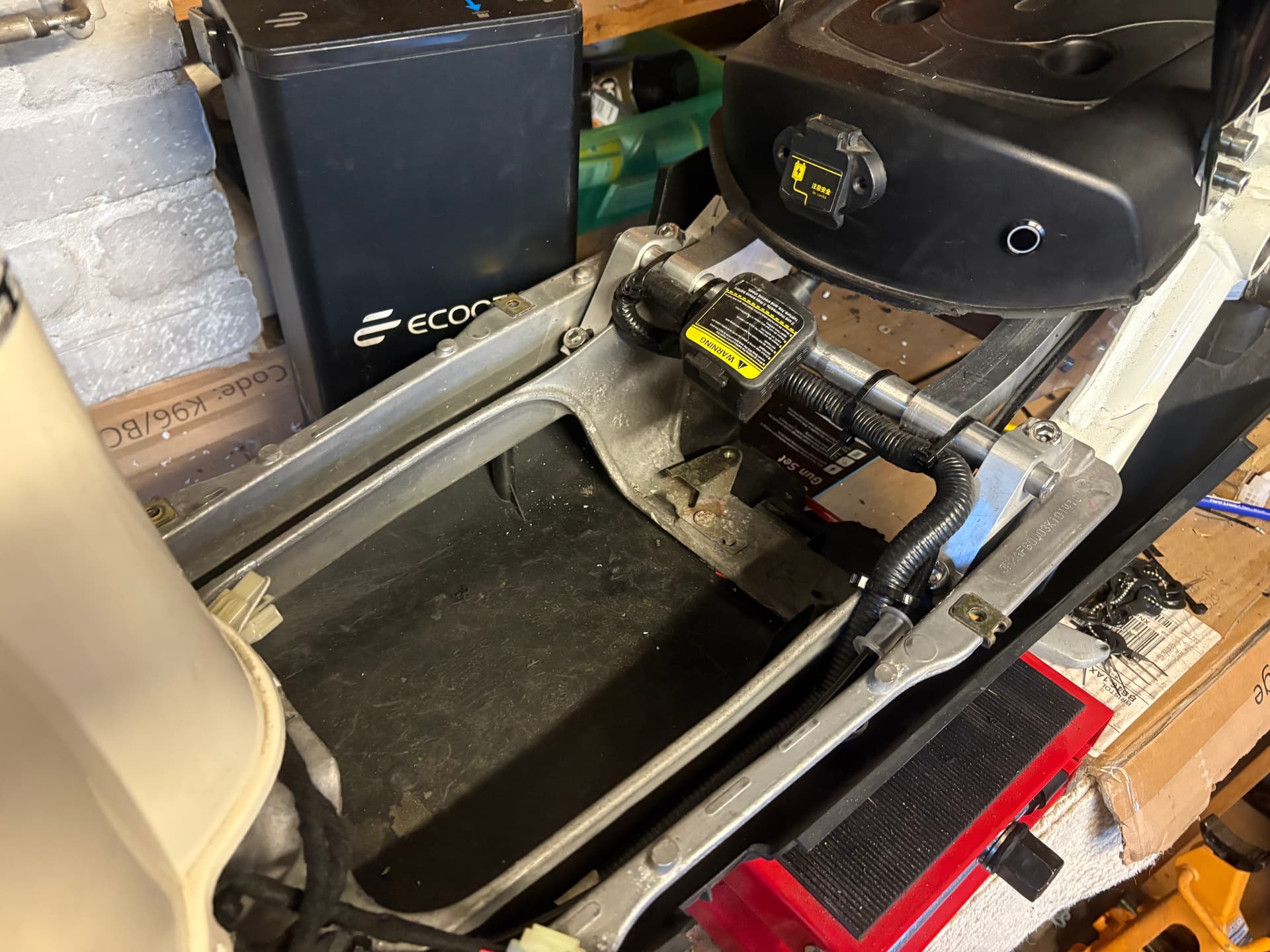
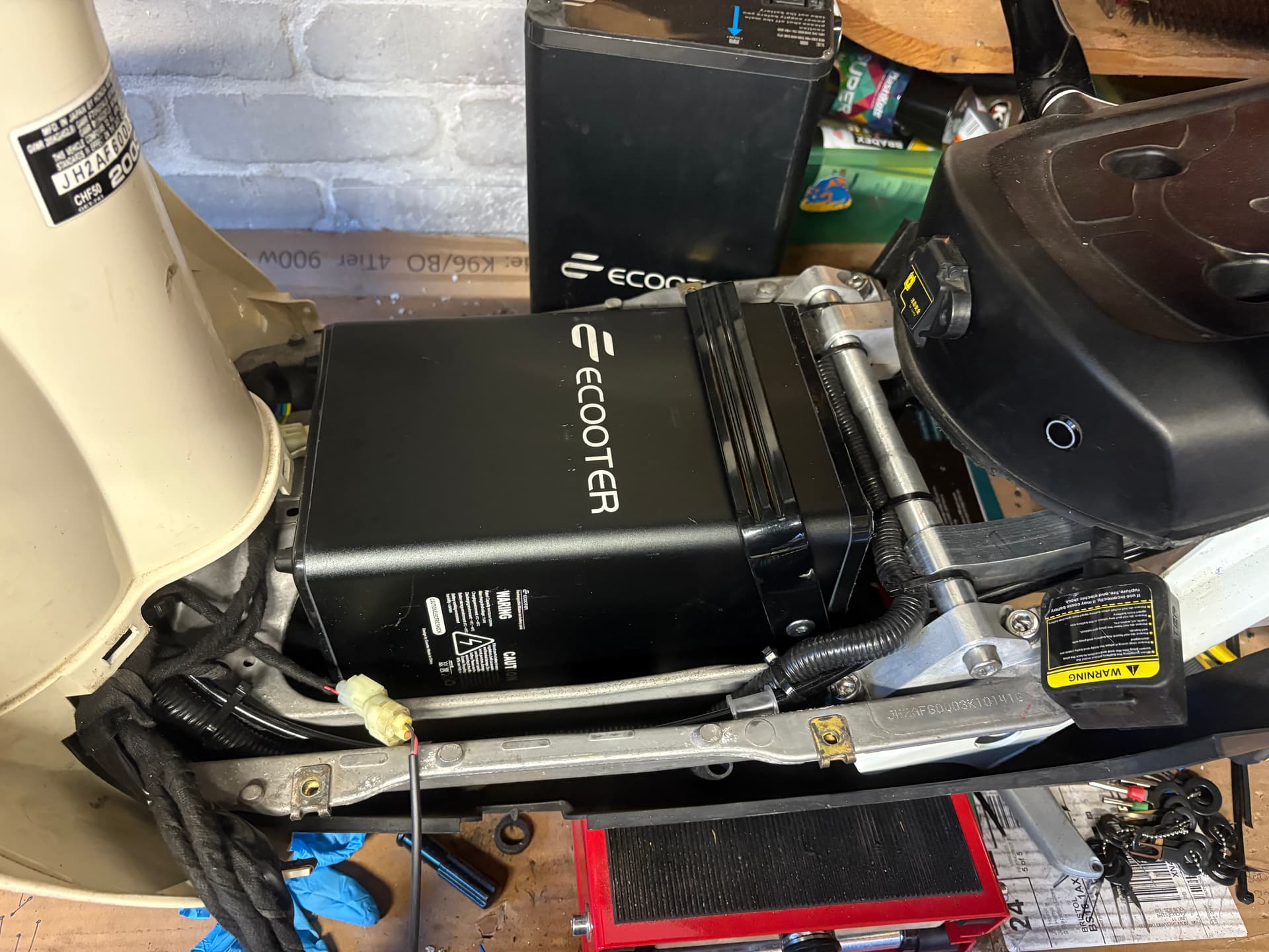
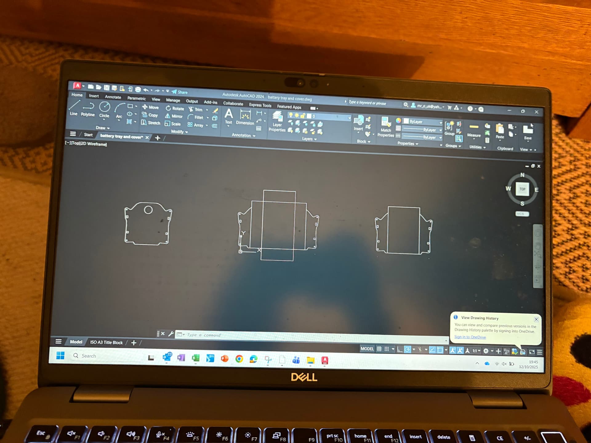
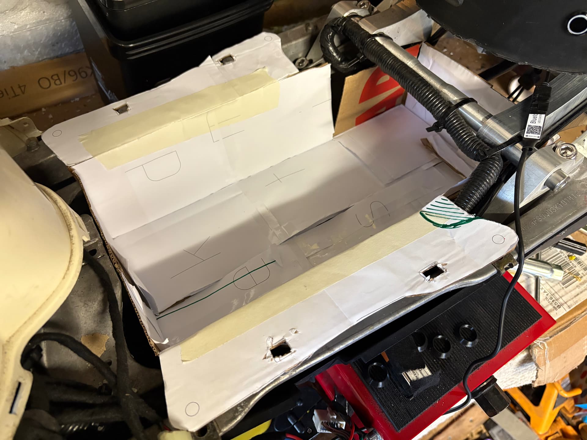
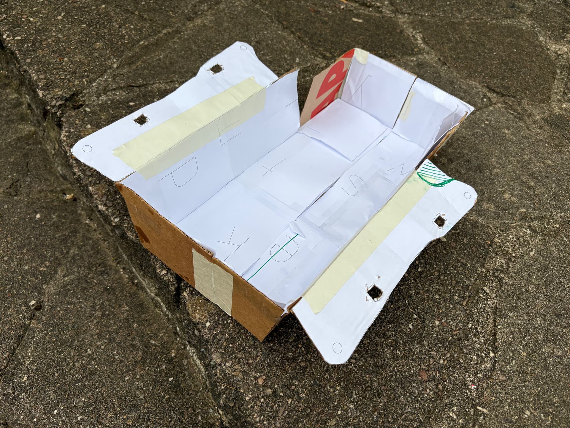
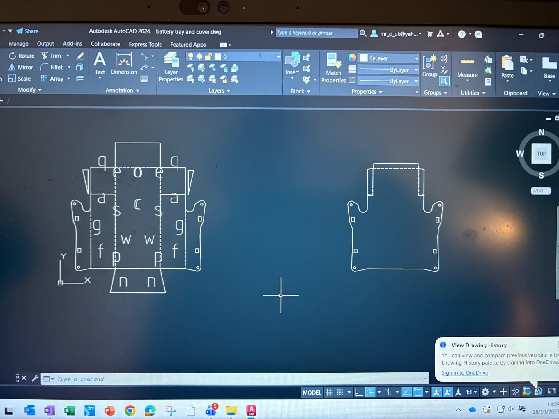
I’ve found a local company who will make custom batteries. So I’m going to see if I can make a battery that fits below the floorboard. It might just be limited on range. So need to make a tray. Doing that in autocad at the moment.
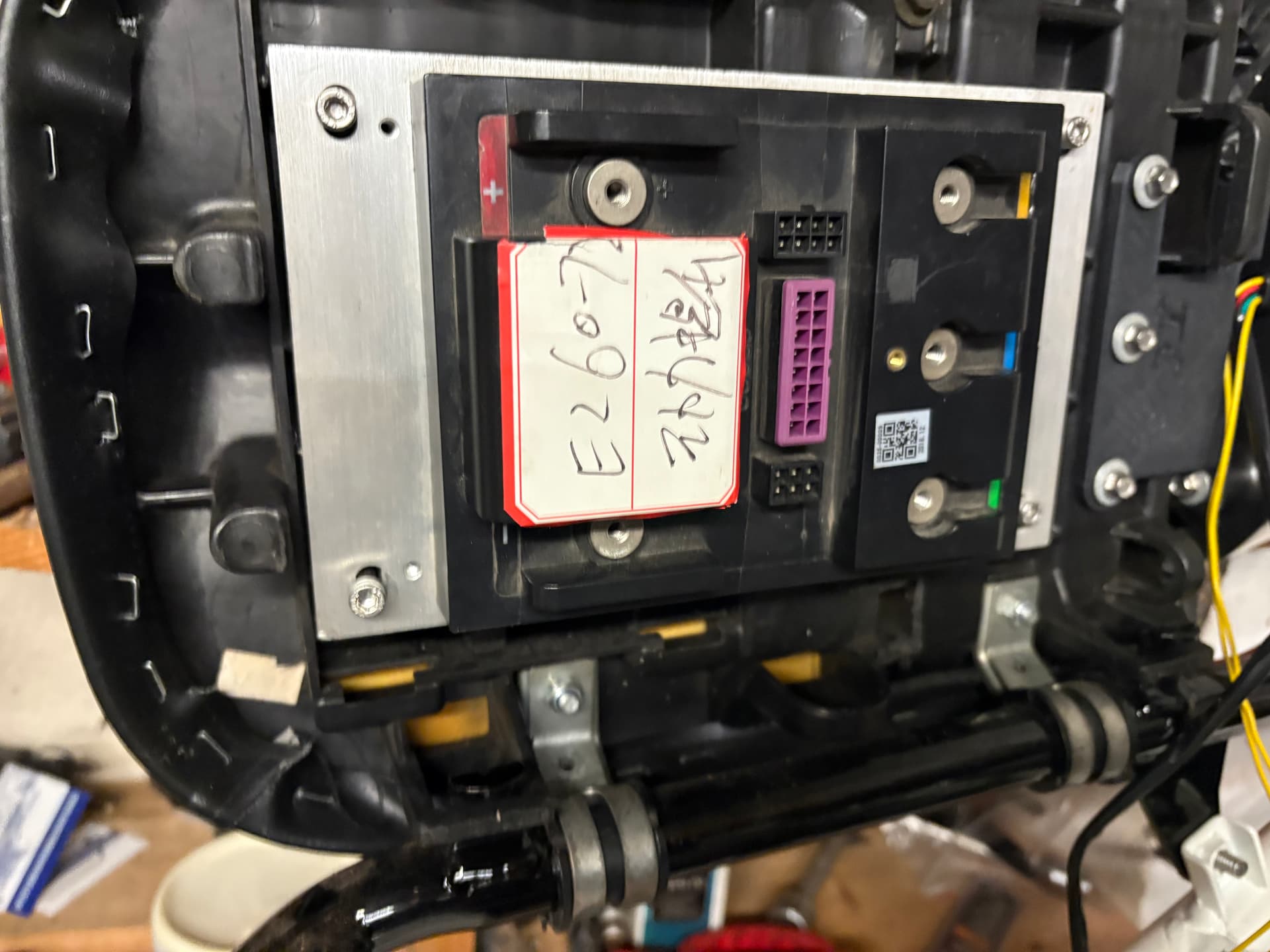
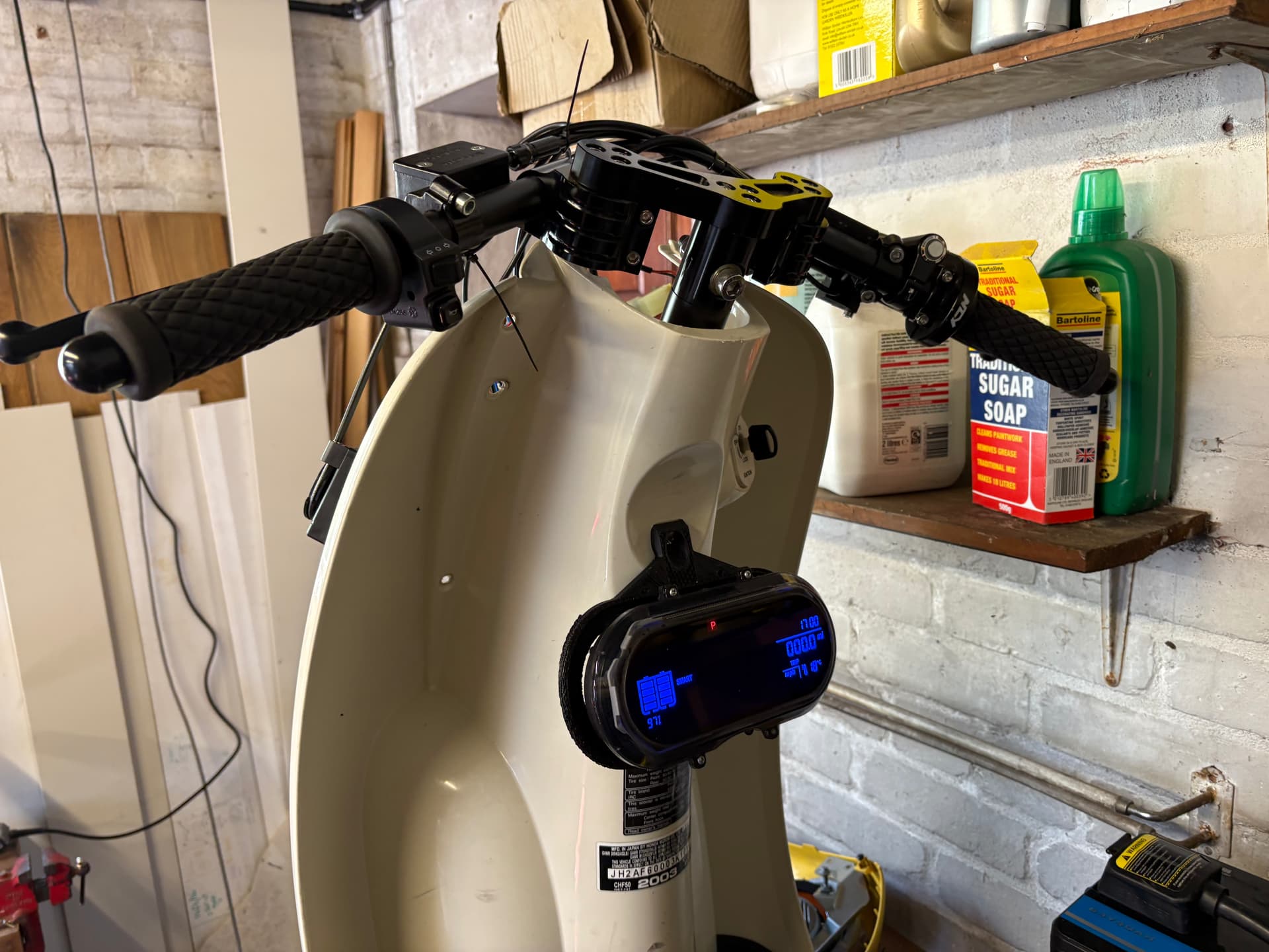
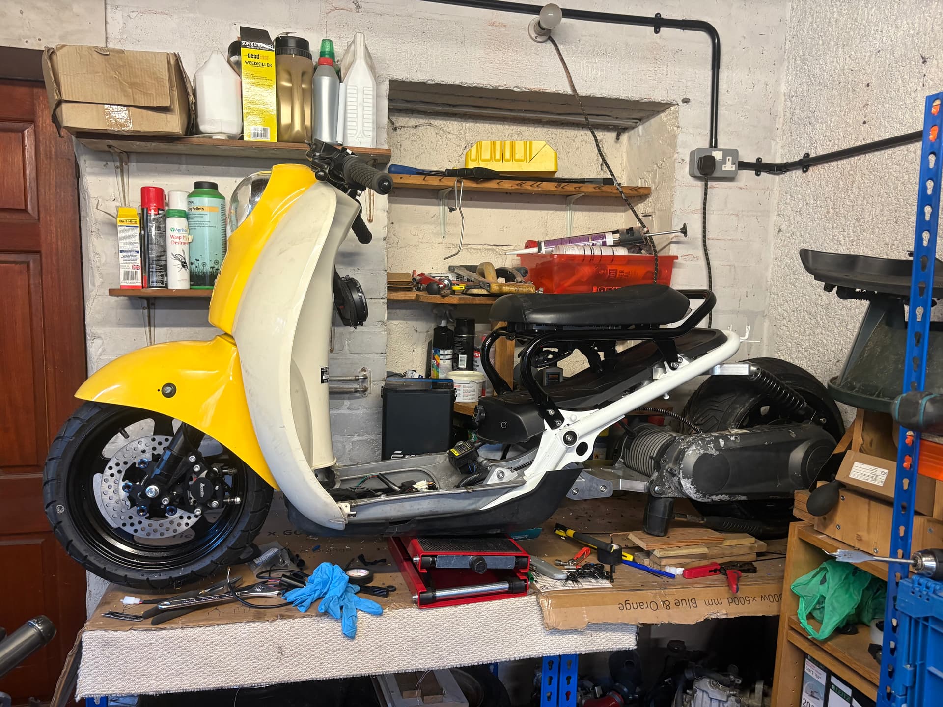
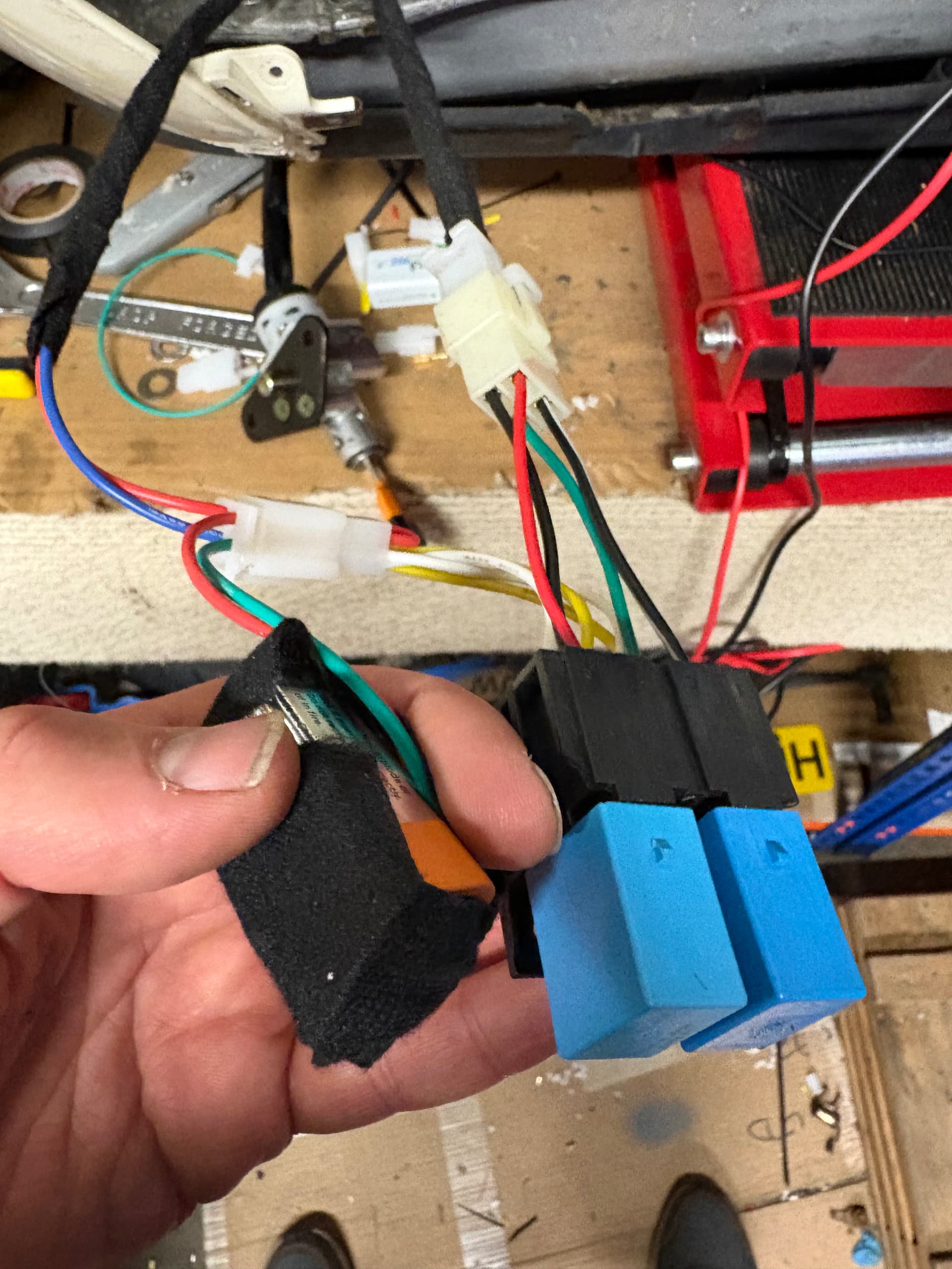
And I’ve spent some time getting the old ignition switch to work with the new one. The old one just connects A to B when on. The new one has C connected to D when off. And then when on, C and D disconnect and E and F then connect. So I’ve had to split it in to two relays and use a NC relay for C to D and a NO relay for E to F. I’ve then fed a positive through the old ignition switch to both relays to switch when on.
Although I can’t find a permanent 12v so am using a 9v battery to feed through the ignition. I may have to do this permanently if I can’t find a permanent 12v!!!
I had some underglow lying around that I was going to install on my Met last year. So fitted that!! Naff, but fun and you can’t see it as its hidden inside the frame. Blue tooth controlled.
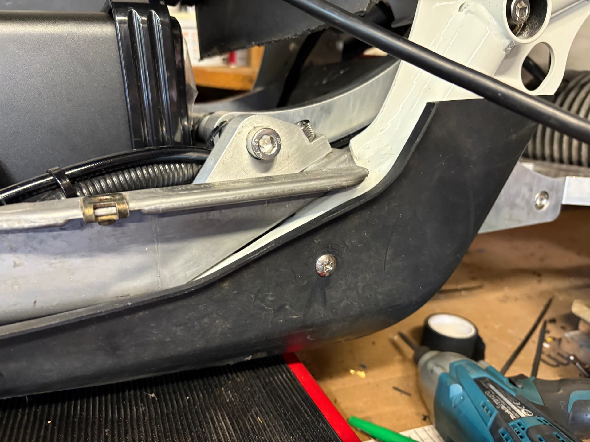
I did use the stock mounts for met on my project. Cut the adaptor up and cut out some metal on the inside of the lower frame. Used longer bolts to mount to frame and threaded them onto the bolt. Wish I took some pics. I’ll try to grab one tomorrow. Great work btw. Now if you could come up with a way to mount the little upper piece of plastic to mount w a vapor is pay for that 3d bracket